Siemens Bit Logic
Published on May24, 2021 | Category: instrunctionShare this Page:
Bit logic instrunction which have only two state either 1 or 0 (true or false). Just like a button which have only two condition on or off. use of bit logic in industry.The two digits 1 and 0 are called bits. in contacts and coils, 1 called true, energized or activate and 0 indicates false, not activated or not energized.Each bit logic instrunction have specified bit address.use of bit logic in industry,start stop motor, machine, condition, monitoring sensors state, solonoid valve command, push button, button logics, trigered next logical function or block etc.
Addressing of bit logic
in bit logic instrunction always use "BOOL data type". size of bool is 1 bits. use foolwing memory area for bit logic
- I input bit example I0.0, I1.0 etc
- M Memory bit example M0.0, M1.0 etc
- O output bit example O0.0, O1.0 etc
siemens plc Normally Open Contact
in normal condition this contact act as open contact and no power flow to next instrunction or contact in same network. if Normally Open Contact set to 1 it will energized and act as close contact so power begains to flow through it and go to next instrunction.
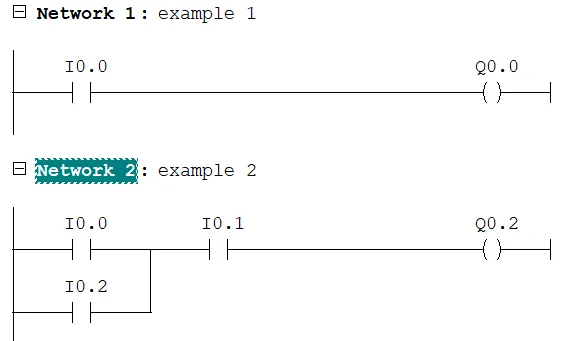
first example address of Normally open contact I0.0 and address of output coil is Q0.0 . normal condition Q0.0 is 0(false) because no power flow through I0.0. if I0.0 is set to 1(true) then output coil is set to 1.
-
in next example
- if I0.0, I0.1, I0.2 is 0 then output Q0.2 also 0. beacuse no power flow to Q0.2.
- if I0.0 set to 1 and I0.1, I0.2 are set to 0 then output Q0.0 set to 0
- if I0.0 and I0.1 set to 1 and I0.2 are set to 0 then output Q0.0 set to 1
- if I0.2 and I0.1 set to 1 and I0.0 are set to 0 then output Q0.0 set to 1. because I0.1 and I0.0 are in parell and act as or gate.
- if I0.2,I0.1 and I0.0 set to 1 then output Q0.0 set to 1.
siemens plc Normally Closed Contact
in normal condition Normally Closed contact act as Closed contact and power flow throught it. if Normally Closed Contact set to 1 it will act as open contact so no power flow through it.
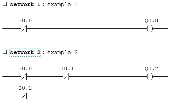
first example address of Normally Closed contact is I0.0 and address of output coil is Q0.0 . in normally state of Q0.0 is 1(true) because power flow through Normally Closed contact I0.0. if I0.0 is set to 1(true) then output coil is set to 0. considered next example in this logic use three Normally Closed contact,
- if I0.0, I0.1, I0.2 is 0 then output Q0.2 also 1.
- if I0.0 set to 1 and I0.1, I0.2 are set to 0 then output Q0.2 set to 1
- if I0.0 and I0.1 set to 1 and I0.2 are set to 0 then output Q0.2 set to 0
- if I0.2 and I0.1 set to 1 and I0.0 are set to 0 then output Q0.2 set to 0. because I0.1 and I0.0 are in parell and act as or gate.
- if I0.2,I0.1 and I0.0 set to 1 then output Q0.2 set to 0.
siemens plc Output Coil
output coil always use for output. state of output coil is depended on previous state of logic. in following example state of output bit move to memory bit
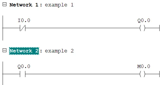
siemens Midline Output
--( # )---,The midline output element saves the logical result of the preceding branch elements. Midline Output is an intermediate assigning element which saves power flow status to a specified address. midline output In series with other contacts , midline output is inserted like a contact.A midline output element may never be connected to the power rail or directly after a branch connection or at the end of a branch.
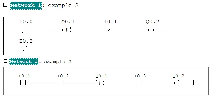
- in first example midline series with two Normaly open contact (I0.0 and I0.2). address for midline output is Q0.1. state of midline is depend on preceding branch elements. when either I0.1 or I0.2 set to 1 so midline output also set to 1.
- in second example midline output is depend on I0.1, I0.2(preceding branch elements) but not depend on I0.3 but output coil Q0.2 is depend on every branch elements.
siemens plc Invert Power Flow
-|NOT|- invert output of preceding branch elements bits. it is work as NOT gate. -|NOT|- invert result of logic operation not affect memory area directely. considered folowing example

- in first example output is set to 1 only when I0.1 is 0, because -|NOT|- invert of preceding branch elements bit.
- in second example a midline output inserted after I0.1 so it store I0.1 status. when I0.1 set to 1 -|NOT|- invert bit of I0.1. Q0.1 is set to 1 when I0.1 and I0.3 or I0.4 is set to 1.
siemens plc set reset flip flop block
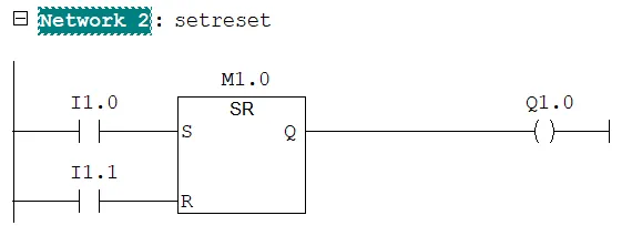
SR (Set-Reset Flip Flop) set or reset bit of the specified address. if input of set S is "1" , and "0" at the Reset R input then bit set to defined address. Otherwise, if the signal state is "0" at the S and "1" at the R input, the flip flop is reset. If "1" at both inputs, the order is of primary importance. The SR flip flop executes first the set instruction then the reset instruction at the specified address, so that this address remains reset for the remainder of program scanning. note: The S (Set) and R (Reset) instructions are executed only when the input is "1". when input "0" has no effect on these instructions and the address specified in the instruction remains unchanged.use when set and reset bit on address
-
in above example set and reset address I1.0 and I1.1.
- if the I1.0 and I1.1 is 0 then nothing is changed.
- if the I1.0 is 1 and I1.1 is 0 then M1.0 is set(1) and output Q1.0 is 1
- if the I1.0 is 0 and I1.1 is 1 then M1.0 is Reset(0) and output Q1.0 is 0
- if the I1.0 and I1.1 is 1 then the reset instruction dominates because of the order. M1.0 is reset and Q1.0 is "0".
siemens plc reset set flip flop block
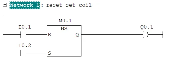
RS (Reset-Set Flip Flop) is reset specified address if the signal state is "1" at the R input, and "0" at the S input. Otherwise, if the signal state is "0" at the R input and "1" at the S input, the flip flop is set. If "1" at both inputs, the order is of primary importance. The RS flip flop executes first the reset instruction then the set instruction at the specified address, so that this address remains set for the remainder of program scanning.
-
in above example reset and set address I0.1 and I0.2.
- if the I0.1 and I0.2 is 0 then nothing is changed.
- if the I0.1 is 1 and I0.2 is 0 then M0.1 is Reset(0) and output Q1.0 is 0
- if the I0.1 is 0 and I0.2 is 1 then M0.1 is Set(1) and output Q1.0 is 1
- if the I0.1 and I0.2 is 1 then the reset instruction dominates because of the order. M1.0 is reset and Q1.0 is "1".
siemens plc Set reset coil
Set and reset Coil are executed only if preceding instructions is "1" (power flows to the coil). both coil are output type coil. in step7 not allowed to use both coil in same line or series with each other.
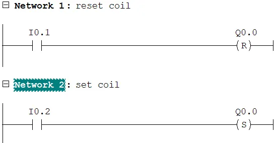
- if I0.1 is set to 1 then Q0.0 is reset
- if I0.2 is set to 1 then Q0.0 is set